
The question is rarely “how many holes does a catalog recommend.” It is whether gas can leave the place it is generated, through a path that still exists after splash, tilt, and debris, without over-pressuring the farthest corner of the box.
Module-level vents and pack-level vents are not two sizes of the same part. One manages local ejecta and neighbor-to-neighbor heat. The other manages the sealed enclosure: daily pressure equalization and, if a cell fails, controlled exhaust away from the cabin and high-voltage joints. Count, placement, and path resistance have to be calculated together. A spare screw-in vent on the lid does not fix a blocked channel inside the stack.
Start from architecture, not from a vent SKU
Three layouts change the answer.
Cell to module to pack. Cells vent into a module case or channel. The module then dumps into a pack plenum. Pack-wall vents are the last orifice to ambient. You are sizing two (sometimes three) restrictions in series.
Cell-to-pack or cell-to-body. The module shell is gone. Pack-level vents and internal ducts must collect gas from many cells without a module “first chamber.” Open area at the pack wall often has to rise, and internal path design becomes the real product.
Hybrid or small sealed boxes. Free volume is smaller, thermal mass is different, and one well-placed dual-function vent can be enough for breathing. Emergency flow still depends on chemistry and whether a single cell can overfill that small volume.
Industry practice published for automotive packs has been at least two vents on a full EV pack, sometimes up to around a dozen on large packs, and often at least one on a hybrid pack. That range is a starting observation, not a specification. SAE’s later pack-venting guidance treats number, position, and discharge direction as integration variables, and treats required open area as chemistry-dependent. Copying a competitor’s vent count onto a different stack-up is how packs pass a drawing review and fail a corner-cell event.
What module-level venting is actually for
A module vent is a local dump path.
Prismatic and many cylindrical cells already have a cell vent or burst feature. When that opens, hot gas and solid ejecta leave at high speed. If the only way out is a single narrow slot above the array, solids arrive first and can clog the slot before the gas peak. Published module work on multi-channel housings makes the same point: one primary channel open on only one end is easier to plug; channels that open to a plenum on more than one side, plus secondary paths above cells, move solids and gas on different routes.
Module-level hardware is therefore less about IP69K on a pretty cap and more about:
- A short, lined path from each cell vent to a collector.
- Enough free section that one failing cell does not pressurize the whole module before the pack sees flow.
- Direction: gas and particles leave toward a planned pack duct, not across busbars and the next cell’s vent face.
- Heat: gaskets and channel walls see a short, severe thermal pulse. Everyday ePTFE breathing membranes do not belong in that jet.
If the module case is not a sealed pressure vessel, the “module vent” may be an opening and a gasketed duct rather than a threaded valve. If the module is sealed for service or coolant isolation, then it needs its own breathing element and an emergency opening, and those two jobs still should not share one small membrane—the same conflict as at pack level.
What pack-level venting is actually for
A pack vent sees the enclosure as a tank.
Daily service: free air volume changes with temperature and altitude. A thin cover and a long gasket line will work-harden if the only leak path is a stretched seal. ePTFE vents equalize that slow differential while holding water and dust to IP67, IP68, or IP69K, depending on the wash and immersion method you actually run.
Emergency service: when module or cell gas arrives in the plenum, pack pressure must stay below the structural limit of the box. Opening pressure of the relief feature is set against that limit, not against a round catalog number. Discharge must be aimed—away from the cabin, charge port, and harness glands.
Pack-level count is then a parallel-orifice problem plus a reliability problem:
- More vents, or a larger vent, lower the pressure rise for a given gas rate.
- Two vents far apart beat two vents in one cluster if the pack is long and internally partitioned.
- One vent can be drowned, iced, or packed with underbody splash. A second vent on another face is redundancy, not decoration.
- Breathing airflow (liters per hour at about 10 mbar) and emergency airflow (liters per second after opening) must be added separately. Summing membrane ratings does not give you emergency capacity.
How to calculate the airflow path
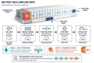
Treat the path as a series of pressure drops. The vent data sheet is only the last term.
1. Name the two flow cases.
Case A is daily equalization. Case B is emergency dump. Do not average them into one “airflow requirement.”
2. Size Case A from free volume and the fastest real temperature ramp.
A sealed volume follows the gas law. If temperature rises and nothing can leave, pressure rises in proportion to absolute temperature. If you instead hold pressure near ambient, volume of air must leave. A simple planning estimate used in enclosure work is:
Q_avg ≈ V × (ΔT / T_ref)
Q is in the same volume units as V. ΔT is in kelvin. T_ref is about 273 K for a rough hour-scale estimate. A 20 L free volume and a 45 K rise then needs on the order of a few liters of air to leave—not a large number, but it must leave during the ramp, through membrane resistance, without pushing the lid past your seal design pressure (often tens of millibars).
Convert that displaced volume into a rate using the shortest charge/drive heat-up you specify, then pick membrane area so the pressure drop at that rate stays below the seal limit. Adding vents in parallel adds Case A capacity only if each vent still sees the same plenum pressure. A vent trapped behind a dead-end rib does not count.
3. Size Case B from gas generation and allowable pack pressure.
Emergency flow is an orifice-and-duct problem. You need:
- An assumed event: one cell, one module, or a defined propagation window.
- A gas volume and a rise time (chemistry and SOC matter; high-nickel systems generally need more open area than many LFP layouts).
- A maximum pack ΔP below cover rupture and below the pressure that collapses cooling plates or lifts busbar supports.
- The free flow area after the relief feature opens, not the membrane face area.
Industry dual-stage examples put emergency flow in the tens of liters per second at a few hundred millibars once the second stage is open. Your number will differ. What does not differ is the rule: the membrane that breathes at liters per hour cannot be the emergency orifice.
4. Add internal path resistance before you add vents.
Walk the gas:
cell vent → module channel → pack collector → pack vent → vehicle exit.
Each bend, mesh, spark arrestor, acoustic baffle, and sudden contraction adds ΔP. A convenient check is: if you apply the target pack ΔP at the vent, does the farthest cell still see a path that can pass the Case B mass flow? If the collector necks down to a 10 mm gap for half a meter, adding a third lid vent does not fix that gap.
For parallel vents, the pack is a network. Flow splits toward the lowest resistance. If all vents sit on the rear wall, a front-module event still has to cross the pack. Place at least one vent (or one duct mouth) near the statistically worst initiation zone—often a center or rear stack in a floor pack—not only where the cover is easy to punch.
5. Derate for the things that are not on the data sheet.
Water film, mud, ice, oil mist, and cell debris reduce both Case A and Case B. Caps and drain geometry protect the membrane for daily life. Emergency paths need a second, larger opening that does not rely on clean pores. If a spark arrestor or particle filter is required, put its pressure drop in the Case B budget on day one.
6. Confirm with the test that matches the path, not the part.
Pressure-cycle and IP tests qualify the breathing face. A ramp test or thermal-event test qualifies the open path. Leak-check after assembly should use the same ports you will have in production, so a dual-channel or testable valve body is a process choice as well as a safety choice.
A practical way to choose count and type
Work the table in this order.
Sealed volumes. List every cavity that can trap pressure: pack, sealed module, junction box, cooling-manifold pocket. Each sealed cavity needs Case A capacity.
Partitions. If foam, cold plates, or module walls create compartments with weak communication, treat them as separate volumes or add a designed transfer opening. One vent on a six-compartment pack is five unvented boxes plus one vented box.
Length and orientation. Packs longer than about a meter, or packs that see pitch and roll, need vents that still work when one end is the low point. Two vents on opposite sides is the usual minimum for a BEV floor pack; more appear when open area for Case B cannot be met with two orifices of the size the cover will allow.
Module strategy. If modules are open to a shared plenum, invest in channels and gaskets at module level and in pack-level relief. If modules are sealed, give each module a defined dump into the pack and keep pack-level vents for the outer shell. Do not assume the module opening is a substitute for pack IP protection.
Vehicle exit. The pack vent is not the end of the path. Chassis rails, underbody shields, and heat shields can turn a well-aimed valve into a random jet. Place pack vents where the vehicle already has a legal, directed outlet.
Part type. Everyday equalization wants ePTFE, hydrophobic and preferably oleophobic, in a housing that survives IP67/IP68/IP69K as specified. Emergency dump wants a set-point opening and a large free section—burst, jettison, dual-channel body, or a separate burst panel. Combining both in one assembly is packaging. Combining both in one membrane is a compromise you should be able to defend with numbers.
What belongs on the drawing
For each vent location: cavity served, Case A target (L/h at a stated mbar), Case B target (open area or L/s at a stated mbar), opening pressure versus cover limit, spray exposure, and discharge vector.
For the path: minimum free section from the worst cell to ambient, including arrestors.
For the assembly: how production will leak-test without destroying the burst feature.
Those lines tell a supplier what to quote. “Battery vent, IP68, qty 4” does not.
Spider(Xiamen) Technology Co., Ltd has worked on ePTFE membranes and protective breathable components since 2016, including pack-oriented explosion-proof valves that equalize in normal use and open for directional relief above a set point, with protection ratings up to IP68/IP69K on the relevant families. The polymer team includes master’s- and doctoral-level engineers; 5%–20% of annual revenue goes to product and process development. Quality systems include ISO9001 and IATF16949. Third-party reports available where applicable include SGS, CE, UL, PFOA-Free, RoHS, and REACH. Products are used in electronics, automotive, new energy, outdoor equipment, and medical devices, and have been supplied to customers in Europe, the United States, Germany, Korea, Japan, India, Russia, Turkey, and other markets. The working idea is integrity builds quality, innovation leads the future: count vents after you have counted paths.
For a free-volume and path review, or for a dual-path layout on a specific pack, contact weitaiyan@spider-amoy.com.
By SST R&D Engineering Team, Spider(Xiamen) Technology Co., Ltd.