
Oil-cooled motors and nearby electronic-control housings fail vents in a way water never does. The housing still needs to breathe. Temperature and altitude still create a pressure differential. A standard waterproof ePTFE vent that passed IP67 on a dry bench can lose airflow after oil mist reaches the membrane. When that happens, the seal—not the membrane—takes the load. Leakage, housing deformation, and water ingress follow.
This article explains how oil mist is generated in oil-cooled e-drive systems and e-control housings, why ordinary vents clog, and what a workable vent specification must include before durability testing starts.
What “oil mist clogging” actually is
Three different oil states share the same cavity. They are not interchangeable, and a vent that survives one will often fail the other two.
Liquid splash. Gears, bearings, and rotor oil-throw throw liquid cooling or lubricating oil onto walls, baffles, and the vent face. Vehicle pitch and braking move the free surface. If the vent looks at a gear mesh or a fill path, liquid oil arrives as a film, not as vapor.
Aerosol / oil mist. High-speed shear breaks oil into fine droplets that stay suspended. This mist is often invisible. It follows gas flow toward the only intentional opening in the housing—the vent. Particle size is small enough to reach the membrane even when splash never does.
Oil vapor. Coil and oil temperatures drive low-boiling fractions out of the cooling oil. Vapor moves with the gas, then condenses on the cooler vent body and membrane. Condensate is liquid oil again, now sitting in the pores.
In a shared-cavity oil-cooled e-drive, all three exist at once. In a separate e-control or inverter housing the liquid splash load is usually lower, but vapor, assembly oils, and adjacent gearbox mist can still wet a membrane that was specified only for water.
Why a standard ePTFE vent clogs
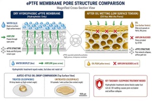
Expanded PTFE works because its pores are small enough to hold a water meniscus and open enough to pass air. That geometry assumes a high-surface-tension liquid. Cooling and transmission oils have much lower surface tension. Once oil wets the pore wall, the meniscus that blocked water no longer forms in the same way, and the liquid occupies the air path.
Hydrophobic treatment is not the same as oleophobic treatment. A membrane rated only against water can accept oil, hold it, and stop exchanging gas. Airflow decay is not linear. After the first wetting event, each pressure cycle pushes more aerosol into the same pores. Industry durability work on oil-cooled e-drives has shown that a membrane-only vent can lose usable airflow early in an aerosol-rich duty cycle, while a construction that coalesces and drains oil keeps exchanging gas far longer. Exact life depends on oil grade, temperature, speed, vent location, and test protocol—so treat any catalog hour or kilometer figure as a method result, not a universal rating.
Once airflow collapses, the housing behaves as if it were sealed. Heat-up raises internal pressure; cool-down pulls a vacuum. Seals flex, gaskets take cyclic load, and water can enter through the same joint the vent was meant to protect. In high-voltage e-drive cavities, an uncontrolled pressure swing is also a packaging and insulation problem, not only a leak problem.
Oil-cooled motor housing vs. e-control housing
Treat the two cavities separately on the drawing. They often get the same catalog vent and then fail for different reasons.
Oil-cooled motor, reducer, and e-axle. The vent sees splash, mist, and vapor. Duty includes high oil temperature, high shaft speed, and frequent thermal cycles. The vent must equalize pressure and keep oil inside the lubrication circuit. A clogged vent that later “breathes” through a leaked seal has not solved the oil problem; it has moved it outside the housing.
E-control / inverter / PDU housing. The primary job is still pressure equalization and condensation control for electronics. Oil arrives as vapor, as mist from a poorly isolated shared wall, or as residue from machining and assembly. A dry-electronics adhesive vent with no oleophobic rating and no pre-filter is the wrong part if the housing shares atmosphere with the oil circuit or sits in the same thermal plume.
Integrated 3-in-1 and 4-in-1 units make the boundary worse: one casting, several functions, one or two vent ports that must serve both oil and electronics constraints.
What has to be true of a vent that lasts
A durable solution is a system, not a sticker.
Oleophobic ePTFE, not only hydrophobic. The membrane must be specified against the actual oil family (cooling oil, ATF, gear oil) at the expected temperature. Oleophobic rating and oil-contact airflow retention after immersion or aerosol challenge belong in the RFQ, not only water-entry pressure.
Coalescing or multi-layer oil separation upstream of the membrane. Mist should become drainable droplets before it reaches the microporous layer. Sorbent media that stores oil will saturate and then block. Oleophobic coalescing media that lets oil drain back into the sump keeps the air path open. Gravity and orientation matter: a vent that cannot drain will fill.
Mechanical shielding. Baffles, labyrinths, and port location reduce splash load before any media sees it. Do not point the inlet at a gear mesh, spray jet, or fill neck. A cover that helps IP69K spray on the outside should not trap oil on the inside.
Pressure equalization sized to the thermal transient. Oil-cooled motors change temperature quickly under load. The remaining airflow after oil challenge—not the dry datasheet airflow—must still relieve seal stress within the duty cycle.
Serviceable mounting when the oil load is high. Threaded or robust snap-fit bodies are easier to inspect and replace than a welded membrane buried under sludge. For powertrain housings, screw-in constructions with a protected membrane are the usual production choice.
How to specify the part so the test is honest
Ask for four results on the same sample, using the project oil:
- Dry airflow and water-entry pressure (baseline).
- Airflow after a defined oil-mist or aerosol challenge.
- Airflow after thermal cycling with oil present.
- Housing leak and pressure-rise behavior with the vent installed in the real boss, including baffles.
IP67 or IP68 remains a system rating. It does not prove oil-mist endurance. Salt fog, humidity, and vibration still apply, but they do not replace an oil-aerosol test.
Also lock the installation details: thread or snap geometry, torque, O-ring material compatibility with the oil, vent axis relative to gravity, and minimum distance from rotating parts. A correct membrane in the wrong hole will still clog.
What Spider supplies for this duty
Spider (Xiamen) Technology Co., Ltd., founded in 2016, develops ePTFE membranes and protective vents for electronics, automotive, and new-energy housings. For gearboxes, differentials, e-axles, high-speed reducers, hybrid units, range extenders, and high-pressure oil-cooled motors, the SST-Porous® oil mist filter breather valve is built to equalize pressure while capturing and separating oil mist and blocking external water and dust.
The construction uses an ePTFE microporous membrane plus multi-layer filtration so mist is taken out by diffusion, interception, impaction, and settling rather than being stored as a wet plug on the membrane face. Protection can be specified toward IP67/IP68 (and IP69K where the assembly and test method support it). Mounting is typically screw-in (common M12×1.5 and M16×1.5 class bodies in glass-filled PA), with snap-fit or custom interfaces when the housing requires them.
Work runs under ISO9001 and IATF16949. Supporting reports such as SGS, CE, UL, PFOA-Free, RoHS, and REACH are available when the program needs them. A polymer-materials team of master’s- and doctoral-level engineers supports membrane structure, oleophobic modification, and housing integration. The company invests 5%–20% of annual revenue in new product and process development and supplies customized venting to 1,000+ enterprises in Europe, the United States, Germany, Korea, Japan, India, Russia, Turkey, and other markets.
The operating idea is unchanged: integrity builds quality; innovation leads the next design. On an oil-cooled housing that only means something if the vent still passes air after the mist arrives.
If you are seeing seal weep, rising cavity pressure, or a vent that looks wet and dead after durability, send the housing layout, oil type, temperature range, shaft speed band, vent boss drawing, and target IP protocol to weitaiyan@spider-amoy.com. The SST R&D engineering team can separate splash, aerosol, and vapor loads and map them to a drainable, oleophobic construction instead of repeating a dry-electronics vent on an oil cavity.
By SST R&D Engineering Team, Spider(Xiamen) Technology Co., Ltd.