
A protective vent only works if air can reach the membrane and liquid cannot bypass it. Most field complaints that look like “the vent failed” start as an installation problem: an undersized hole, oil on the adhesive land, over-torque on a thread, a weld that burned the film, or a label placed over the active area. The membrane itself may still meet its water entry pressure. The assembly does not.
This note covers installation best practices for ePTFE protective vents on electronics, automotive, new energy, outdoor, and medical housings. It is written for process engineers, quality, and designers who freeze the hole and the work instruction—not for a catalog page. The methods come from more than ten years of application work at Spider(Xiamen) Technology Co., Ltd, where vents are specified as a system with the housing, not as a sticker.
Treat Installation as Part of the IP Rating
IEC 60529 and ISO 20653 rate the finished enclosure. They do not rate a loose vent on a bench. Hole diameter, wall thickness, surface energy, torque, weld energy, and whether the inner face is blocked all change the result. Write the install recipe into the drawing before PPAP or first-article. If the recipe lives only in a supplier email, the second shift will invent a new one.
Confirm three things before the first production part: the vent part number and lot, the housing feature (hole, boss, weld rib, or adhesive land) matches the datasheet, and the operator can see the membrane after install. A vent that disappears under foam, potting, or a nameplate is no longer a vent.
Prepare the Housing Before You Open the Bag
- Hold hole diameter and roundness to the vent drawing. Snap-in and screw-in parts are intolerant of an oval punched hole.
- Deburr both sides. A sharp edge cuts adhesive liners and nicks O-rings.
- Clean the land. Finger oil, mold release, cutting fluid, and powder from sanding are the usual reasons adhesive vents lift after heat aging.
- Check surface energy on low-energy plastics (PP, PE, some painted metals). If water beads on the land, treat or choose a different adhesive / mechanical form.
- Keep the inner volume clear. Design a keep-out so potting, insulation, and cable ties cannot press on the membrane.
Adhesive Vents: Clean Land, Full Wet-Out, No Touch on the Membrane
Adhesive discs are the most sensitive to process discipline and the easiest to get wrong at speed. Use the liner and the recommended dwell. Do not handle the membrane face.
- Wipe the land with the solvent approved for that resin. Let it flash off completely. Wet solvent under the ring creates a weak bond that looks fine at 25 °C.
- Peel the liner immediately before placement. Dust that lands on open adhesive becomes a leak path.
- Center the active area over the hole. The adhesive ring must sit on solid wall, not hang into the opening.
- Apply even pressure for the time in the datasheet. A thumb tap is not a process. Use a flat press foot sized to the ring, not a pointed tool on the membrane.
- Respect open time and full cure before IP or wash testing. Acrylic systems often need hours, not minutes, to reach rated peel.
Interior mount is more forgiving for UV and weather. Exterior mount needs a UV-capable adhesive, a land that sheds water, and a check that paint or powder coat was applied before—not after—the vent. Do not paint over the membrane.
Weldable Vents: Energy Window Beats Peak Power
Ultrasonic and thermal welding lock a membrane patch to a plastic housing without adhesive. The failure mode is almost always energy: too little leaves a dry weld and a leak; too much melts the support layer or closes pores at the weld rib.
- Match the patch backing to the housing resin. PET-backed patches and PP housings are not interchangeable by habit.
- Use a weld rib or energy director designed for the patch thickness. A flat wall wastes energy in the horn instead of the joint.
- Freeze amplitude, weld time, trigger force, and hold time as a set. Change one variable at a time during DOE.
- Inspect the inner face after weld. A brown ring or shiny collapsed film means the pores at the edge are gone. Scrap the part; do not “touch up.”
Snap-In Vents: Hole Quality Is the Process
A snap-in vent is only as good as the molded or machined hole. If the hole is large, the barb does not engage and the O-ring or sealing lip never compresses. If the hole is small, the operator hammers the part and cracks the housing or the vent body.
Specify hole diameter, draft, and lead-in chamfer on the housing drawing. Measure first-off parts with a pin gauge, not a caliper across a draft. Push the vent to the designed stop—do not leave it proud “to make it easier to service.” Confirm extraction force on a sample so field technicians cannot pull it out by hand unless the design intends service.
Screw-In Vents: The O-Ring Seals, the Thread Does Not
Threaded vents fail most often from the wrong torque or a missing O-ring. Under-torque leaves a gap. Over-torque flattens the O-ring, cracks a plastic boss, or twists the membrane carrier.
- Use the thread standard on the drawing (metric fine vs coarse, NPT vs parallel). NPT tapered threads and parallel O-ring threads are not mixed on the same boss.
- Lubricate the O-ring only if the vent supplier allows it, and only with a media compatible with the elastomer and the ePTFE.
- Start by hand to avoid cross-threading. Finish with a torque tool, not a long wrench “until it feels tight.”
- On metal housings, check galvanic pairing and coating at the boss so corrosion does not grow under the O-ring.
- Do not apply thread sealant over an O-ring face unless the drawing says so. Paste in the air path is a clog, not a backup seal.
Place and Orient the Vent After the CAD Freeze
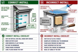
Install location is an installation decision as much as a design decision because harnesses, labels, and brackets appear after the first model. Keep the active face off ponding surfaces. A vertical side wall with a drip edge beats a horizontal lid.
If the product sees IP69K or a wash bay, do not aim the jet at the membrane. A small shroud or offset boss is cheaper than a higher WEP membrane that still takes a direct 80 °C lance. Inside the box, leave a clear cone of air. Foam pressed against the inner face turns a breathable membrane into a closed wall.
Protect the Membrane Through Handling and Downstream Process
ePTFE is mechanically tough in tension and easy to close with the wrong contact. Ban pointed tools, tape across the face, and stacked parts that rub membranes together in a tote.
- Leave the protective liner on until the last possible station if the part ships with one.
- Schedule painting, powder, conformal coat, and potting before the vent is installed, or mask the vent with a fixture that does not crush the film.
- Keep oils, mold release, and washer detergent off the face. Oleophobic treatment resists wetting; it does not make the part immune to a puddle of coolant.
- Do not leak-test with a method that forces liquid through the membrane above its WEP and then call the part a reject. Match the test pressure to the specification.
In-Process Checks That Catch Bad Installs
Visual inspection is necessary and not sufficient. Build a short gate that matches the risk.
| Check | What “good” looks like | Typical miss |
|---|---|---|
| Position | Hole fully covered; ring on solid wall | Offset disc, weld patch short of the rib |
| Membrane face | Clean, unwrinkled, unblocked | Fingerprint, crease, label, foam |
| Retention | Snap seated; torque in window; weld flash even | Proud snap, painted-on torque, burned weld |
| Air path | Inner keep-out clear after final assembly | Harness tie or insulation on the face |
| Function sample | Airflow / WEP still in spec after install | Only a dunk test on an unaged first article |
Sample airflow after install on a defined cadence. A weld or press that looks cosmetic can still close pores. Spider(Xiamen) Technology Co., Ltd can support incoming and post-install measurement methods when the drawing calls for a number rather than “vent present.”
Failure Modes That Start at the Bench
| What you see in the field | What usually happened at install |
|---|---|
| Water after wash, membrane still white | Bypass at adhesive edge, O-ring, or weld—not pore wetting |
| Cover deformed, condensation inside | Vent blocked internally or painted / labeled over |
| Vent missing or loose after vibration | Hole oversize, snap not seated, torque below window |
| Oil-wetted face, lost WEP | Hydrophobic-only film in an oily process, or coolant dripped at assembly |
| Cracked plastic boss | Over-torque or hole too small for a snap-in body |
Work Instructions Worth Freezing
- Print the vent PN, housing feature, torque or weld recipe, and keep-out on one page.
- Show a photo of a good part and three common defects next to the station.
- Define who removes the liner and when.
- Ban unmarked tools that can touch the membrane.
- Re-train when the housing color, paint, or vent revision changes—surface energy and hole size move with those changes.
Where Factory Reality Differs by Industry
Electronics and outdoor equipment. High mix, adhesive and weldable parts, frequent last-minute labels. The risk is covering the vent and painting after install.
Automotive. Snap-in and screw-in volumes, oil mist on the line, IATF process control. Freeze torque, hole SPC, and fluid exposure at assembly. Spider(Xiamen) Technology Co., Ltd works under ISO 9001 and IATF 16949 so the vent process can sit inside that system rather than beside it.
New energy. Large metal boxes, threaded vents, high heat after install. Confirm torque on coated bosses and that insulation blankets are cut around the inner face.
Medical and instruments. Cleaners and traceability dominate. Record lot on the device traveler. Do not wipe the membrane with an unapproved disinfectant at final clean.
When to Ask for an Install Review
Request a joint review when you change housing resin or paint, move from prototype adhesive parts to welded production, raise the rating to a defined IP68 depth or IP69K, or add a downstream process that can coat the face. Send the hole drawing, wall thickness, install photos, and the work instruction—not only the vent datasheet.
Founded in 2016, Spider(Xiamen) Technology Co., Ltd has spent a decade on ePTFE membranes and protective vents for electronics, automotive, new energy, outdoor equipment, and medical devices. Products support enclosure targets of IP67, IP68, and IP69K when the housing and installation are designed together. Documentation such as SGS, CE, UL, PFOA-Free, RoHS, and REACH is available where the application requires it. A master’s- and doctoral-level polymer team invests 5%–20% of annual revenue in material and process work, including how membranes survive welding, torque, and wash. The operating idea is integrity builds quality, innovation leads the future: publish the install limits, then hold them.
For an installation review, weld or torque window, or a customized vent and housing feature, contact weitaiyan@spider-amoy.com. Include the housing drawing, target IP or ISO 20653 rating, and photos of the current station.
By SST R&D Engineering Team, Spider(Xiamen) Technology Co., Ltd.