SST Porous waterproof and breathable product installation method
2023-08-21
Ⅰ、SCREW-FIT ENCLOSURE PROTECTION VENTS
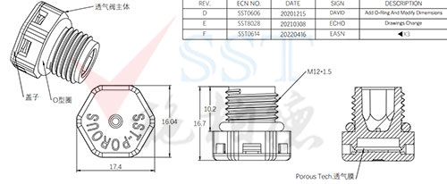
1、product display
2、Suggested housing opening design method (Take the M12*1.5 vent valve as an example)

Installation method when the shell wall thickness is less than 3mm

Installation method when the shell wall thickness is greater than 3mm
3、installation guide
- Clean the mounting surface and the area where the mounting screw secures the vent to remove any contamination and allow the surface to dry after cleaning;
- The ideal installation position is in the vertical direction of the shell or the bottom of the shell, this position will prevent any liquid and dust from accumulating inside the breather valve;
- Insert the screw-fixed vent hole of the breather valve into the housing so that the threads are properly aligned, and then screw into the housing;
- After ensuring the vent thread is correct, tighten the vent to 0.6-1.0Nm;
- A hexagonal or hexagonal wrench is optional for fixing various types of breather valves;
- Chamfers are recommended for optimum O-ring seals when the wall thickness is appropriate.
Ⅱ、BUTTON ENCLOSURE PROTECTION VENTS
1、product display
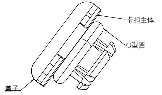
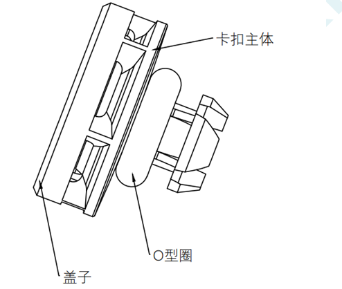
2、Suggested housing opening design method

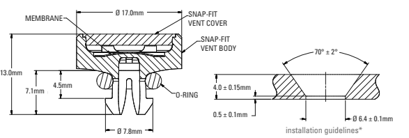


3、installation guide
-
Clean the mounting surface and the area where the snap-on vent will be installed to remove any contamination and allow the surface to dry after cleaning;
- The ideal installation position is in the vertical direction of the shell or the bottom of the shell, this position will prevent any liquid and dust from accumulating inside the breather valve;
-
Chamfer recommended for optimum O-ring seal when wall thickness is appropriate;
-
Install the vent between 150 N and 300 N until an audible “click” is heard ensuring seal integrity.
Ⅲ、Adhasive VENTS
1、product display
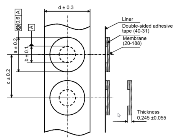


2、product structure


3、installation guide
-
Clean the surface on which the adhesive-backed vent is installed to remove any contamination and allow the surface to dry after cleaning;
-
Housings for vents, accurate placement of vents can be improved through the use of markings, recessed areas, or targeted areas;
-
Apply slight finger pressure (recommended 15PSI) on the rubber ring of the adhesive-backed venting membrane to ensure that the venting product can be firmly bonded to the shell;
-
Do not attempt to reposition the vents after installation, as this will cause the membrane to deform and fail;
-
A dwell time of at least 24 hours is required before use or testing of finished components.
Ⅳ、Welding VENTS
1、product display


2、Typical structure of welded vent membrane
The welded assembly consists of a SST Porous membrane with or without support material, which can be attached to the plastic shell by heat fusion, ultrasonic welding, bonding or overmolding to form a waterproof and breathable assembly.
Typical welded vents include:
- Efficient SST Porous PTFE vent membrane, as a hydrophobic and oleophobic barrier layer for particles, while allowing gas to pass through;
-
Plastic housing – can be integrated with the filter media, can be easily installed into the housing, and can be selected from various thermoplastics (PBT, PA, ABS, PPS, etc.), elastomers (TPE) and other materials.
3、packaging options
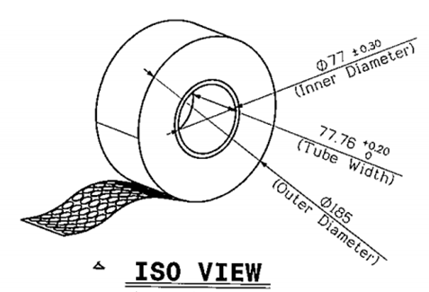
Packaging Form 1 – Roll:
-
Attachment on light-adhesive continuous release paper: Each polyethylene core has 1000~10000 waterproof and vent membranes
-
The roll film should be sealed in a clean bag unless otherwise specified
-
Optional protective release paper
Packaging Form 2 – Bulk:
- Packed in stackable trays and sealed in clean bags, ready to be picked by robots or other automated equipment; packed in bulk in clean bags.

